
Introduction
A little while ago (about 6 years to be exact) the best antenna I had for 145MHz was the 1/4-wave mag-mount antenna on the roof of my car. So I decided I wanted a bit more gain. I was able to get more by using a pair of end-fed 1/2-wave antennas. This gave about +3.5dBd, which is about 6dB more than the 1/4-wave antenna. The antenna is still nailled to the side of the house and I can access four repeaters, between Uppsalla and Stockholm.
Now that I have become a bit more active on the bands I want more than just to talk on the local repeater. I want VHF SSB, so I need a decent horisontal Yagi. I also want to put out a respectable signal on FM, vertically polarised. Location can be more important than gain, but having a bit extra gain to start with helps.
This project is about a cheap way of building a colinear antenna for VHF 145MHz, and having about 10dB more gain than that little 1/4-wave magmount I have not used for 6 years. The actual gain of this antenna is +7.5dBd.
It consists of five half-wave dipoles, four of which are end-fed by means of a 1/4-wave stub to invert the phase. The center element is centre-fed at 200 Ohms by means of a 4:1 coaxial balun from the 50 Ohm coaxial feed cable. Elements and coils are all wound from just two lengths of wire, without the ned for joints, junctions, soldering or loads of bolts. The most complicated bit is knocking the 12 nails in four bits of wood.
Materials
The materials consist of 9 metres of multi-strand power cable, with a conductor diameter of about 1.5mm. I used 32-strand 10-Ampere cable. You also need three sections of 50mm Diameter plastic drainpipe: the sort that just pushes together with rubber seals. The only other thing needed is four coil formers, so let us start with those.
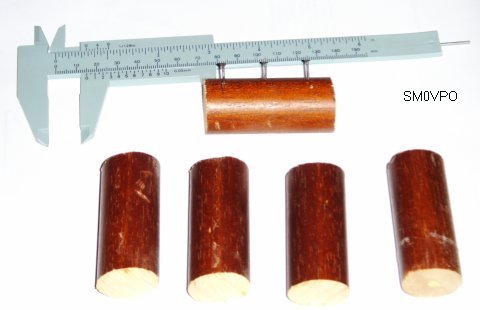
The materials needed for the stub coils.
Measure the wire diameter, WITH INSULATION and multiply by 16. Mine is 2.5mm so my coils will be 2.5mm x 16 = 40mm long. My formers are 60mm long, so I have 10mm free at each end when I hammer in the nails (panel pins).
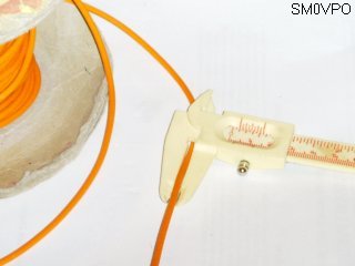
You need to measure the wire diameter.
The next thing to do is to find the formers. I used 26mm Diameter wooden dowel. This I stole from the bedroom and guest room windows. Maj-Lis likes those wooden rod curtain supports, and she has not missed 60mm missing from each of the four windows :-) but if anyone tells her I will kill them!
Construction
The object is to wind a 1/4-wave stub: that is 1/2-wavelength of wire, folded in half, the two ends being the feed points. The stub will be coilled up, so calculate your 1/4-wave and multiply by 0.8 to get the true length. With 26mm Diameter formers, 145MHz, this is exactly 408mm, which just happens to be exactly five turns. So I need to wind five turns, then another five turns in the opposite direction. I shall hammer three nails into each former at 20mm spacing, to wrap the wire around. It looks like this:
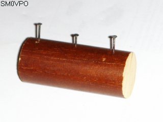
The support nails for the coil, and the coil added.
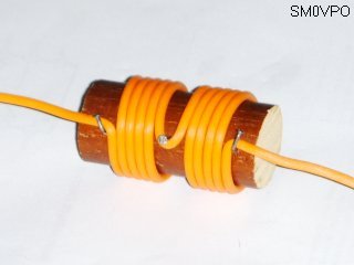
Bear in mind that you assemble each half of the antenna from one end, winding the coils as you go along. The stub coils just hang in the wire. The end nails are bent over to form hooks.
Element wire lengths are 96% of a calculated 1/2 wavelength (150000 / MHz = mm). For 145.000MHz this works out to exactly 1 metre. So all you have to do is to wind the coils at 1 metre intervals, then cut the center of the centre element to feed the antenna. All the coils then hang on the wire.
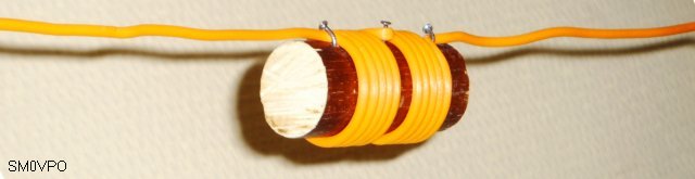
The finished stub positioned in the antenna wire.
Feeding the Antenna
I connected the feeder to the antenna by means of a "sockerbit" connector block: the kind you use to connect light power cables. You need two contacts, but you could use three and use it to couple the three coaxial braids (shields) together. Note the bit of clear plastic tube around the connector. This tube takes the weight of the lower element and prevents the feed point and balun being drawn down into the pipe.
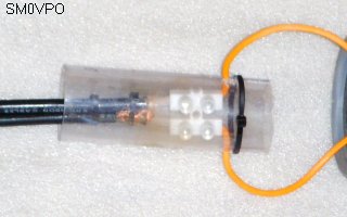
The connector feeding the antenna elements.
The balun is composed of a bit of coaxial cable. It must be 1/2-wavelength long, multiplied by the velocity factor (VF) given in the cable specifications. UR76 has a VF of 0.66 so I need a length of 0.66 x 1040mm = 686mm. You should then short-circuit both ends and use a Grid Dip Oscillator (GDO) to check the balun resonance is indeed 145MHz.
If you do not have the luxury of a GDO, then you can build my design. Alternatively you can assemble the feeder and balun, terminate it with a 220 Ohm resistor, then check the VSWR across the entire 2 metre band. If it is best at 144MHz and poor at 146MHz, then you need to cut a bit off the balun coax, reassemble and test again. The VSWR should be almost perfect at 145MHz.
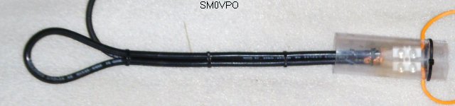
The completed balun feeding the antenna.
So to take a step back and look at the overall antenna, with all elements, coils, feeder and coaxial balun, we have a simple antenna with just a few coils. Remember that there is no break in the wire from the top to the feed-boint, and from the feed point to the bottom.
The complete antenna arrangement.
Supporting the Antenna
The antenna is enclosed in plastic drainpipes. These things just push together and come in 2 metre lengths. This is bad news because the elements total 2.6 + 2.6 metres. So you need four of these tubes. One for the upper element, one for the lower element, and one for the horisontal feed and support tube. The fourth tube is cut into shorter bits to extend two vertical tubes by about 600mm. The bottom tube can be extended by much more so that it can stand on the roof, or floor, for support.
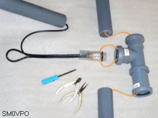
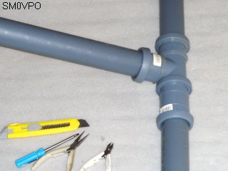
The center assembly.
I have also used a 40mm Diameter plastic tube to support the center of the antenna inside the pipe. I cut two slots in it and fed the feeder through it. The weight of antenna wire would otherwise put strain on the top support and feed point.
The assembled antenna center.
Conclusion
Like all good projects, it should be nicely finished off. This antenna I threaded inside 5.5 metres of plastic drainpipe. At the centre I fitted a "T"-junction so that I could feed the antenna without having the feeder and balun drooping beside the antenna elements. The feeder should be lead straight out horisontally. Fit a top-cap to keep water out. The bottom cap should have a hole in it to prevent build-up of moisture.
You could alternatively hang the antenna from a tree, or any other support. Keep the antenna as far as possible from any metal structures, but antennas of this type must of necessity be mounted close to some form of support structure.
For best results you should mount the antenna as high as possible. There is absolutely no reason why this antenna cannot be mounted horisontally to form a dual-beam antenna. You should really use a rotator in this event. The plastic tubes may need some form of guy wire support, especially if mounted horisontally. For vertical use you may need no support, or possibly the "ships mast" type of support, to stop the antenna bending in the middle.
The "ships-mast" principle.
The "bare-bones" antenna can be built, tested and operational within one hour. It is easy to construct, and gives a very nice result. From rudimentary tests with 25 metres distance I believe that I have achieved the full 7.5dBd gain. Thats 10dB better than my little rusty 1/4-wave in the attic :-) I also have probably 10dB more due to the elevated location of the final antenna. If you want to check the gain yourself, do
Tidak ada komentar:
Posting Komentar